![CAE 아토즈 [CAE AtoZ]](https://tistory1.daumcdn.net/tistory/4851315/skinSetting/c853faceba4f4ee7bb954261b8401f1d)
1. 3D Mechanical의 Ropes소개

위의 그림에서와 같은 구성으로 Rope 관련 Component Icon을 지원합니다.
3D Mechanical Library 에서 Ropes component icons은 winch 및 sheave 사이에서 linear force를 생성하기 위해 사용,

위의 Rope end component Icon은 3D Mechnical library의 component Icon과 Rope component Icon을 연결하는 Component Icon입니다.
2. Simple demo #1
Demo 목표
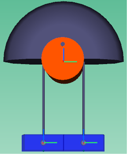
고정 도르래의 왼쪽 고리에는 Mass 1kg(LM)의 물체 연결, 오른쪽에는 Mass 10kg(RM)의 물체 연결하여 time domain에서의 물리량 변화를 관찰해 보도록 하겠습니다.

위의 그림과 같은 이미지를 생각해 볼 수 있습니다.

Amesim의 Work flow를 따라 Sketch mode에서 위의 이미지와 같은 형식으로 모델을 구성합니다
Parameter mode (F11) 클릭 → Yes → m6dofassembly 클릭
아래와 같은 상태로 보이는 것을 확인 하실 수 있습니다.

다시 Parameter mode에서 component icon의 Parameter를 아래와 같이 입력합니다.

상기 Parameter 입력 후 m6dofassembly 모델의 반영
여기 모델에서 Rope의 길이는 sheave의 rope sliding을 고려할때와 하지 않을때 각 아래의 수식을 참조하여 결정됩니다.

Rope의 length 길이는 LM (Port 1) or RM(Port2) 부터 고정 도르래(sheave)의 고정 위치 - sheave radius의 값으로 조정할 수 있다.

Sheave diameter의 경우 Parameter 모드에서 sheave diameter 값을 통해 조절가능하며 Assembly 환경에서는 sheave width에 대해 animation 요소로 조절가능하다.
위의 내용을 살펴보면 Parameter mode에서 component icon별 position을 정의하면 정상적으로 동작하는 것을 볼 수 있다.
추가적으로 Positive, Negative 옵션에 따른 차이는 아래와 같습니다.

'Simcenter 기술 자료 > Simcenter Amesim' 카테고리의 다른 글
| [2D Mechanical] Ropes component활용 Converting Demo 소개 (0) | 2023.04.25 |
|---|---|
| [3D Mechanical] Rope Simple demo #2 (0) | 2023.04.24 |
| [2D Mechanical] PLMCONT000 접촉 모델의 수렴 문제 원인과 해결 방법 (0) | 2023.04.20 |
| [3D Mechanical] Pivot Junction의 Orientation 설정 방법과 회전 모션 구현 (0) | 2023.04.14 |
| [Simcenter Amesim] Simulation 결과를 저장(Export) 방법 #3 (0) | 2022.03.02 |


댓글